The core of this project is to advance the robotics and computer vision technology needed by a garden trimming robot, then to develop and demonstrate that robot and finally evaluate the performance of the new technological components and the robot as a whole.
Proposed physical components: The complete package can be illustrated by the cartoon sketch:

Model sketch of the robot
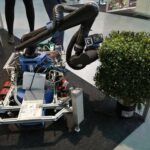
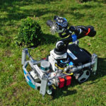
While only a schematic representation, the cartoon illustrates what we are aiming for: a small consumer mobile robotic base with a manipulator arm and an end effector based on a typical garden plant cutting tool. The right side of the above figure shows a modified Bosch Indego robotic base, which we propose to adapt for this project. The Indego is a wirelessly connected, battery-powered robot base, capable of 50 cm/sec travel. The unmodified vehicle is 52×70 cm, with up to a 30kg load carrying capability, and can climb slopes up to 35%. It has wheel encoders, an inertial measurement unit, lift-up-sensor, and a bumper sensor.
On top of this base we plan to mount a 6 degree of freedom Universal Robots UR5 arm, which will allow adaptive alignment to cutting locations up to 85 cm in all directions. While 85 cm is too small for many real gardens, it is adequate for demonstration of the principles and will allow the evaluation needed for further development to proceed. An image of the proposed arm is at the left in the figure below. The arm weighs 18 Kg, has 0.1 mm repeatability, and can carry a 5 Kg payload. There is currently a small control box that may have to be re-engineered for mounting on the Indego base.
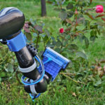
At the right of the figure is a sketch of a possible cutter that can be used as the end effector. Based on a typical hedge trimmer, this device will have powered sliding blades.


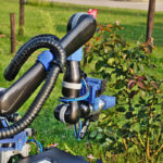
A wide angle stereo camera system will be mounted on the base of the robot. One possibility is the colour RGB Skybotix sensor shown in the figure below. It weighs about 110 gm, and can provide a 30 fps feature-based stereo coupled to 6 DoF inertial data. The sensor physical dimensions are 133x40x57 mm and has a ROS interface. A fisheye camera will be mounted at the front and rear as well. Also mounted on the arm near the cutter will be another small video-rate sensor (possibly the SoftKinetic sensor shown below, or another Skybotix sensor, depending on the performance outdoors in sunlight), with a lower resolution colour image. Medium to high resolution is required to reconstruct branches and leaves. A laptop with a GPU will be on board for control and communications. Development of this platform will require innovations in clipper design, load and stability management, and power management.
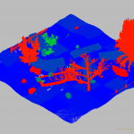
Possible experimental domain: For experimentation and evaluation purposes, we will construct a small garden (e.g. 12m x 6m) similar to that in the sketch below.
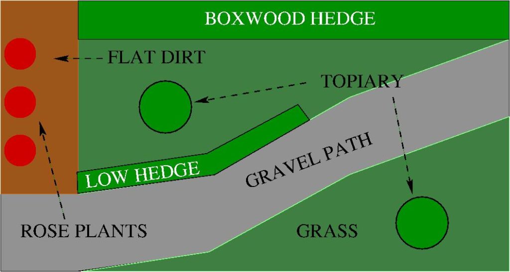
Possible experimental domain
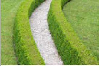
Hedge example
The garden shows the types of features that will be addressed in the project. There are three types of navigable surfaces: mowed lawn, small gravel and flat soil, and there will be small slopes in the grass and soil. The Indego is capable of travelling on all three surface types, but wheel slip will require vision-based localisation. There are also obstacles in the garden like bushes, fences, a pool, etc. Garden features are allowed to change over time just as in a real garden. There are four types of garden feature that will be subject to pruning by the robot.
The ‘boxwood hedge’ is intended for demonstrating the ability to produce extended flat surfaces. The ‘low hedge’ demonstrates regular trimming on all sides of the bush, whereas the ‘topiary’ plants will demonstrate more sophisticated trimming. More exotic ornamental shapes could be considered, but are not necessary for developing and demonstrating the core principles which are trimming of flat and curved shapes. Finally, there is a small rose garden with several bushes for evaluating stem recognition and trimming.
Integrating the visual inputs with the actions implied by the user-specified trimming tasks, which will lead to the three system demonstrators. This integration will be facilitated by the use of the interfaces defined by ROS (Robot Operating System). Our system components to be usable by others within the ROS conventions. The demonstrators will lead to a full system execution, where the robot navigates from one location in the garden to another, avoiding obstacles, servos adjacent to a specified plant to be trimmed, and then trims it.
Outline of project data and relationships: The relationships between the different components of the project and associated research are outlined below. The diagram focuses on how the outputs of the various processes are used by each other, rather than the processes themselves, which are described in more detail later. The three subsystems in the demonstrator are colour coded light red, green and blue.
- Visual data capture and analysis (blue boxes): This subsystem produces the 3D information needed by the robot planning and task execution subsystems. Using both the vehicle and arm mounted stereo video systems, a combination of shape-from-X processes extract a 3D point cloud with associated surface normals that describes the currently observed scene. This point data is organised into 3D surface patches that describe the surfaces of the ground and bushes. Complementary image region descriptions are also extracted from the intensity data.
The surface and region data are grouped together into larger structures (proto-objects) that represent the opjects in the garden. These proto-objects are labeled using information about the garden, both of a general nature about e.g. the ground, and specific information about the shapes and locations of particular plants from the garden sketch map.
- Action specification and planning (green): This subsystem takes the user’s sketch map and trimming specifications and produces both navigation plans to align the robot with the target plant, and also trimming plans to restore the desired shape to the target plant.
- Robot task execution (red): This subsystem uses the navigation and trimming plans, along with the 3D visual data and recognised garden structures, to navigate the robot into a suitable trimming location near to the target plant and servo the clipper into the appropriate position to perform a cutting operation. These will repeat until the trimming plan is complete.
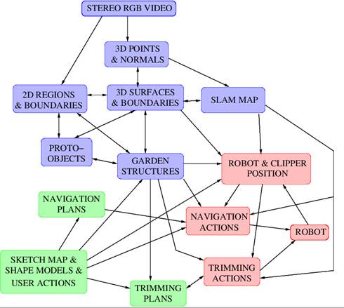
Architecture of the system
Outline of visual sensors and operations: The visual data will come from a number of video cameras, some placed on the vehicle and some placed on the robot arm. The current plan is to have 4 pairs of cameras: two narrow view stereo video sensors placed on the vehicle body and arm, plus two wide view stereo video pairs, one forward facing and one back facing. Two of the potential sensors are the Skybotix and SoftKinetic sensors outlined above.
Five primary representations are derived from the raw data: edges, regions, SLAM 3D, binocular stereo 3D, motion stereo 3D. The region and edge descriptions are computed from the colour and intensity data, initialised largely by traditional image analysis edge detection and region finding processes. One novelty in this project is the use of feedback from the fused 3D point clous, 3D surfaces and surface boundaries to refine the original shape-from-X processes and thus the derived scene descriptions, which feed into the proto-object and scene structure analysis. As with the intensity analysis, the 3D image and video analysis algorithms are initialised from traditional image, video and depth image data; however, they also have feedback inputs from the intrinsic scene descriptions, which will lead to improved 3D and scene descriptions. For example, dense stereo calculations depend on image point matching. When near surface boundaries, the cameras see differing amounts of the background scene, which cannot be completely matched. Both intensity and scene edge data can be used to discover where stereo matching is invalid, and thus improve the correspondences, which in turn lead to better XYZ, surfaces and surface boundaries. In a similar manner, estimates of the 3D scene and its surfaces will feed back into the SLAM and motion stereo processes, to reduce correspondence ambiguity and thus increase accuracy and reduce false matches. The use of feedback data streams is an important aspect of the project because: 1) the abundance of largely similar small features like plant leaves during close plant observation is likely to lead to considerable correspondence matching problems, and 2) false 3D shape recovery and consequent damage to the bushes is not acceptable.
We have chosen multiple 3D imaging processes to enhance reliability when working in an outdoor environment. While using the same sensor, the data streams fuse 3D information from binocular stereo, motion stereo and shape from motion. Each approaches the extraction of 3D from a different theoretical perspective. We believe that the fusion of the three will produce a robust 3D scene shape description, which will also enhance the performance of the individual processes by feedback from the fused representation.
Because the robot and clipper will be targeted at a real application, the algorithmic processing will need to be at close to real-time speeds. Thus, as well as researching algorithms that produce better spatial accuracy and fewer erroneous descriptions, the project will also be investigating CPU and GPU implementations for speed, and algorithmic simplifications that can greatly improve speed for small losses in competence.
Outline of robot navigation and trimming planning: A sketch map similar to that above will be used by the robot to guide its actions, with the assumption that potential users of the robot will have a simple user interface (not part of this project) for specifying the garden. While not metrically accurate, the map will provide the approximate feature locations needed for robot localisation and navigation with the 3D sensor data. The robot will acquire an initial mapping of the garden recording the state in which it should be kept. The sketch map, in combination with the initial SLAM-based map, will also specify the location and desired shape of the plants to be trimmed. (We assume that the trimming is for maintenance of the shapes rather than the initial creation of the shapes, which may require specialist skill over many years.)
Outline of robot navigation and trimming execution: The robot will undock from its charging station, and using the sketch map as an approximate map, will exploit the SLAM-derived map plus the 3D sensor data (see below) plus its inertial measurements to navigate to the approximate trimming location, and then servo to the positions relative to the plant required for the trimming. The trajectory will consider both obstacles and the desired robot orientation and position for the cutting task. Multiple robot positions may be needed for completion of each trimming task, thus requiring visual evaluation of the state of the task and replanning.
The cutting operation assumes that the vehicle is approximately in the correct position for trimming. Trimming will require the cutting tool to approach the plant surface at the correct location, with the correct orientation. The vehicle based stereo system will have observed the global shape of the plant during the vehicle’s approach. At this point, the fine detail stereo system mounted on the manipulator arm will observe the plant surface more closely, relative to the cutting tool. The fine detail stereo will be used to servo the tool into the desired location and orientation for the cut.
The garden navigation and trimming task will lead to research and engineering innovations in these areas:
- sketch map plus SLAM based navigation (development of new techniques for localisation to an inaccurate map, rather than a metrically accurate map),
- limited space navigation and placement using a non-holomorphic vehicle base leading to cooperative planning between the base and the manipulator position systems,
- servoing of the arm and clipper to the desired trimming location, adjusting the servoing in response to the changed shape of the trimmed surface and movement of the plant under the contact forces from the clipper,
- registered the observed noisy 3D plant shape to the sketch model of the desired shape (only small out-growth is assumed),
- creating multiple-stage trimming plans based on robot position and the difference between the observing and desired out-growth is assumed),
- creating multiple-stage trimming plans based on robot position and the difference between the observed and desired plant shape,
- engineering of the Indego base to carry the arm and maintain stability during travel and in response to the reactive forces that arise while trimming the plants.